
Electrical engineers and hobbyists alike encounter alternating current (AC) waveforms in various electronic systems, from power distribution to audio processing and digital electronics. Understanding the properties, parameters, and behavior of AC waveforms is crucial to designing and analyzing these systems. Are you ready to unravel the mysteries of AC waveforms and unlock a world of potential applications?
Key Takeaways
AC waveforms are generated through electromagnetic induction and consist of sinusoidal and non-sinusoidal varieties, used in various electronic systems.
Key parameters such as amplitude, frequency, period & phase are essential for understanding their behavior & properties.
AC waveform analysis is widely used to optimize performance/efficiency & diagnose electrical faults[1] across power systems, electronics testing etc.
The Basics of AC Waveforms
AC waveforms are the foundation of modern electrical systems, as they represent the variation of voltage and current over time. These waveforms are generated through electromagnetic induction, as explained by Faraday’s Law, where the motion of a rotating magnet in a stationary coil produces a voltage proportional to the rate of change in magnetic flux. AC waveforms differ from their direct current (DC) counterparts, which maintain a continuous DC voltage and do not change direction. The two most common types of AC waveforms are sinusoidal and non-sinusoidal, comprising square, triangular, and sawtooth varieties.
Sinusoidal waveforms are the most advantageous in AC circuit theory, consisting of positive and negative halves. These waveforms are produced by rotating electrical generators and are the most common waveform type due to their smooth, continuous nature. On the other hand, non-sinusoidal waveforms, such as square, triangular, and sawtooth, possess distinctive characteristics and are employed in various electronic systems, like digital electronics and communication systems.
Sinusoidal Waveforms
Sinusoidal waveforms, also known as sine waves, are the most common AC waveforms, generated by rotating a coil of wire through a magnetic field. This process induces a voltage in the coil, resulting in a sinusoidal waveform output. The sinusoidal waveform follows a sine function and exhibits a cyclic variation of its value with respect to time. These waveforms are ubiquitous in numerous applications, such as power transmission, audio and video signals, and control systems.
In AC circuit theory, sinusoidal waveforms are advantageous due to their smooth, continuous nature, allowing for a more stable and predictable signal. This property makes them ideal for use in various electronic systems that require consistent, reliable signals, such as power distribution and communication systems.
Non-Sinusoidal Waveforms
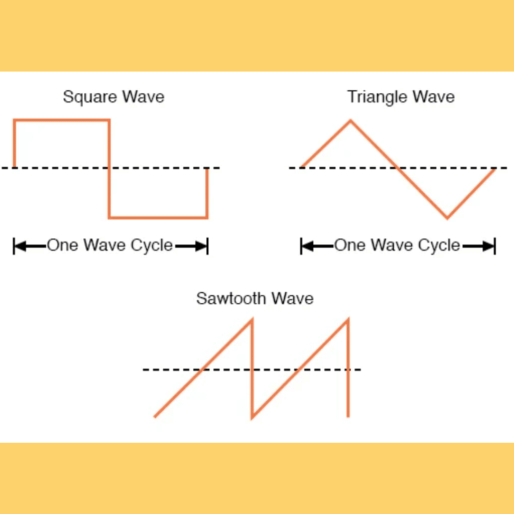
Non-sinusoidal waveforms, such as square wave, triangular, and sawtooth, offer unique characteristics and applications in various electronic systems. Here are some examples:
Square waveforms have two states, ‘ON’ and ‘OFF’, and are commonly used in digital electronics.
Triangular waveforms are periodic with equal rising and falling times, exhibiting a linear increase and decrease with a sharper peak edge.
Sawtooth waveforms have a distinctive shape and can be either positive ramp or negative ramp.
To determine the average value of non-sinusoidal waveforms, mathematical techniques such as the mid-ordinate rule, trapezoidal rule, or Simpson’s rule can be employed. These waveforms are utilized in various electronic systems, including digital electronics, power electronics, and communication systems.
Key Parameters of AC Waveforms
Analyzing AC waveforms requires understanding of key parameters such as amplitude, frequency, period, and phase. These parameters describe the behavior and properties of the waveform, offering a deeper understanding of how various electronic systems function.
For instance, the characteristics of an AC waveform include:
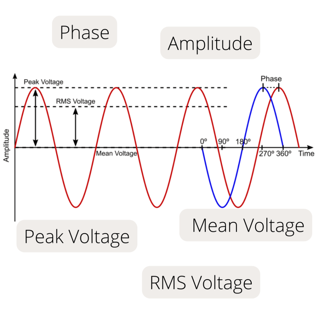
Amplitude: Signifies its maximum value at a specific instant, measured from the zero baseline.
Frequency: Quantifies the number of cycles completed in a given time period, typically measured as the number of cycles in one second.
Period: The time required to complete one full cycle of a waveform, inversely proportional to frequency.
Phase: The angular displacement of the waveform from the zero baseline, measured in degrees.
Understanding these parameters is key to analyzing AC waveforms and their various applications.
Amplitude
The amplitude, representing the maximum value that a waveform reaches at any moment, is a vital parameter in understanding AC waveforms. It measures the magnitude of the alternating current or voltage, typically in volts or amps. Determining the amplitude of a waveform aids in understanding its behavior and characteristics, such as intensity and potential distortion.
In AC waveforms, the amplitude can be measured using:
Peak value: represents the highest point of the waveform, measured from the zero baseline
Peak-to-peak value: represents the difference between the highest and lowest points of the waveform
Average value: represents the average value of the waveform over a complete cycle
Understanding the amplitude of AC waveforms is essential for designing and analyzing electronic systems, as it provides valuable information about the behavior and properties of the waveform.
Frequency and Period
Frequency and period are inversely related properties of AC waveforms, which are essential to understanding their behavior and characteristics. Frequency is measured in Hertz (Hz) and represents the number of cycles a signal completes in one second. The period, on the other hand, is the interval in which a waveform completes one cycle, and is typically measured in seconds or degrees.
To determine the frequency of an AC waveform, one can assess the period of the wave and calculate the reciprocal of that time value (in seconds). By understanding the relationship between frequency and period, we can analyze the performance and efficiency of electronic systems that rely on AC waveforms, such as power distribution networks and communication systems.
Phase
Phase is a property of sinusoidal waveforms that represents the time difference between two waves with the same frequency, measured in degrees. It denotes the position of a waveform at a certain moment in time and enables us to comprehend the comparative timing and synchronization of multiple signals. Phase is pivotal in AC circuit analysis, as it influences the behavior of components such as capacitors and inductors and facilitates the determination of the overall performance and efficacy of the system.
The phase difference between two waveforms can be measured using various formulas and methods, such as:
Computing the phase shift between two waveforms
Using a phase meter or oscilloscope to directly measure the phase difference
Analyzing the phase of AC waveforms to gain insight into the functioning of electronic systems, such as power distribution networks and communication systems, and optimize their performance.
Analyzing AC Waveform Values
Understanding the behavior and characteristics of AC waveforms requires analysis of their different values, such as average, RMS, and peak values. The average value of an AC waveform can be calculated over a half cycle for sinusoidal waveforms, while mathematical techniques can be employed for non-sinusoidal waveforms. The RMS value, on the other hand, is a modified average value used for AC systems, calculated by taking the square root of the mean of the square of the voltage or current.
The peak value, representing the highest point of an AC waveform measured from the zero voltage line, is vital for understanding its amplitude. Similarly, the negative maximum value, which represents the lowest point of the waveform, is also crucial for a comprehensive analysis. Analyzing these waveform values, including peak voltage, offers insights into the behavior and properties of AC waveforms, aiding in designing and analyzing electronic systems that rely on alternating current.
Average Value
The average or mean value of an AC waveform is an essential parameter that provides insight into its behavior and characteristics. By considering all the instantaneous values, for sinusoidal waveforms, the average value can be calculated over a half cycle. This value can be determined using the formula V_avg = (2 * Vm)/pi for sinusoidal waveforms. The average value of a pure sinusoidal waveform is invariably equal to 0.637 times the maximum voltage.
Mathematical techniques such as the mid-ordinate rule, trapezoidal rule, or Simpson’s rule can be used to determine the average value of non-sinusoidal waveforms. These techniques can calculate the area underneath the waveform. These techniques allow us to analyze the behavior and characteristics of various types of AC waveforms and their respective applications in electronic systems.
RMS Value
The RMS (root mean square) value is a modified average value that is crucial for understanding the behavior and characteristics of AC waveforms. It is calculated by taking the square root of the mean of the square of the voltage or current, and represents the effective value of the AC signal. This value is important for:
Evaluating power consumption
Determining the magnitude of the signal
Accurately representing the real power or effective value of the alternating current.
The RMS value of a sinusoidal waveform can be determined by taking 0.707 (or 70.7%) of its peak amplitude value. This value is essential for the accurate calculation of power consumption in AC circuits, as it takes into account both the magnitude and direction of the waveform, allowing for the precise calculation of the average power utilized in the circuit.
Peak Value
The peak value of an AC waveform is another essential parameter that provides insight into its behavior and characteristics. This value represents the highest point of the waveform, measured from the zero baseline. Understanding the peak value is crucial for determining the amplitude of AC waveforms, as it provides valuable information about the behavior and properties of the waveform.
To determine the maximum or peak value of an AC waveform, one can assess the maximum value that the waveform attains during each half cycle measured from the zero baseline. This value is the most significant value of either voltage or current and is essential for understanding the amplitude of AC waveforms and their applications in electronic systems.
Form Factor and Crest Factor: Assessing Waveform Shape
Evaluating the shape of AC waveforms helps understand their behavior and properties. Two important tools for evaluating waveform shape are Form Factor and Crest Factor. Form Factor is the ratio between the average value and the RMS value of an AC waveform, while Crest Factor is the ratio between the RMS value and the peak value of an AC waveform. Both of these factors provide information about the relationship between average, RMS, and peak values, which can be used to analyze the waveform’s shape and characteristics.
Comprehending these factors is key to evaluating AC waveforms and their applications in various electronic systems like power distribution networks, communication systems, and audio processing systems. By analyzing the Form Factor and Crest Factor, we can gain valuable insights into the behavior and properties of AC waveforms, which are essential for designing and analyzing electronic systems that rely on alternating current.
Form Factor
Form Factor is an important parameter in evaluating AC waveforms, as it provides insight into their shape and distortion. It is the ratio between the RMS (root mean square) value and the average value of an AC waveform. By calculating the form factor, we can determine the degree of distortion and the quality of the waveform.
A high form factor in AC waveforms signifies a greater degree of distortion in the waveform, indicating that the waveform deviates more from a perfect sinusoidal shape. Conversely, a low form factor implies a waveform with minimal distortion or more closely resembling a pure sinusoidal waveform. Analyzing the form factor allows us to better understand the behavior and characteristics of AC waveforms and their applications in electronic systems.
Crest Factor
Crest Factor is another important parameter that offers information about the shape and characteristics of AC waveforms. It is the ratio of the RMS value to the peak value of an AC waveform. The Crest Factor provides insights into how much the waveform deviates from its average or RMS value, thus offering information about its amplitude and potential distortion.
In sinusoidal waveforms, the Crest Factor is typically 1.414, whereas in non-sinusoidal waveforms, it can deviate from 1.414, indicating a distortion in the waveform. By analyzing the Crest Factor, we can gain insights into the functioning of electronic systems, such as power distribution networks and communication systems, and optimize their performance.
Practical Applications of AC Waveforms
AC waveforms play a significant role in various electronic systems, with their practical applications spanning:
Power generation
Power distribution
Audio processing
Digital electronics
For instance, AC waveforms are employed in power generation and distribution systems due to their ability to enable the efficient transmission of electrical energy over long distances. AC waveforms are also used in audio processing systems to represent and manipulate audio signals, ensuring accurate amplification, mixing, and reproduction.
Non-sinusoidal waveforms, such as square, triangular, and sawtooth, are employed in digital electronics to symbolize binary signals and clock signals. Moreover, AC waveforms enable the transmission and processing of digital information in electronic circuits, facilitating the functioning of various systems, such as motor control, robotics, and signal processing.
Understanding the practical applications of AC waveforms is essential for designing and analyzing electronic systems that rely on alternating current. By gaining insights into the behavior and properties of AC waveforms, we can optimize the performance and efficiency of these systems, ensuring their safe and dependable operation.
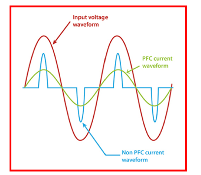
Challenges and Solutions in AC Circuit Analysis
AC circuit analysis introduces various challenges including comprehending the theory and practical implementation of AC electrical circuits, managing reactive power losses and power factor correction, and analyzing circuits with phase shifts between voltage and current. To overcome these challenges, engineers employ mathematical techniques, such as phasor analysis, impedance analysis, and Laplace Transform, to analyze waveform values and properties.
Furthermore, Fourier series can be employed in the analysis of AC waveforms, expressing a non-sinusoidal periodic waveform as a sum of sinusoidal waveforms, allowing for the examination of the waveform’s harmonic content and the identification of its frequency components. By utilizing pertinent tools and software for calculations and simulations, engineers can streamline the circuit analysis process and ensure accurate results.
By addressing these challenges and implementing effective solutions, electrical engineers can analyze AC circuits with greater precision and accuracy, optimizing the performance and efficiency of electronic systems that rely on alternating current.
Real-World Examples of AC Waveform Analysis
Practical examples of AC waveform analysis can be observed in diverse scenarios like power systems, electronics testing, renewable energy systems, medical diagnostics, and communication systems. In power systems, electrical engineers utilize AC waveform analysis to comprehend the behavior and characteristics of alternating current, designing and optimizing power systems, calculating power consumption, evaluating power quality, and diagnosing electrical faults.
In audio processing and digital electronics, AC waveform analysis is employed to represent and manipulate audio signals, ensuring that they can be amplified, mixed, and reproduced faithfully. By understanding the behavior and properties of AC waveforms, engineers can optimize the performance and efficiency of electronic systems, ensuring their safe and dependable operation.
AC Waveform Measurement Tools
Engineers rely on measurement tools such as oscilloscopes to effectively analyze AC waveforms. Oscilloscopes:
Display voltage over time
Measure key parameters such as period and frequency
Come in various types, such as digital, analog, and mixed-signal oscilloscopes
Oscilloscopes are essential for accurately measuring AC waveform parameters.
By using oscilloscopes, engineers can determine the amplitude of a waveform by calculating the number of vertical divisions between the highest and lowest points of the signal. They can also measure the phase difference between two waveforms by comparing the time difference between corresponding points on the two waveforms. With these tools in hand, electrical engineers can effectively analyze AC waveforms and optimize the performance of electronic systems that rely on alternating current.
Summary
In conclusion, understanding and analyzing AC waveforms are essential for designing and optimizing electronic systems that rely on alternating current. By exploring the fundamentals of AC waveforms, their key parameters, and the tools used to measure them, we can gain valuable insights into their behavior and properties. With this knowledge, we can optimize the performance and efficiency of various electronic systems, such as power distribution networks, communication systems, and audio processing systems, ensuring their safe and dependable operation.
Frequently Asked Questions
What are the three AC waveforms?
The three AC waveforms are Complex Waves, Square Waves, and Triangular Waves, all of which can be seen in the illustration.
What is the basic AC waveform?
The basic AC waveform is a sinusoidal or sine wave that periodically changes its polarity at regular intervals. It produces an EMF with a positive maximum value and a negative maximum value which reverses at regular intervals, with one full reversal known as the waveforms period.
What are the parameters of the AC waveform?
The important parameters of the AC waveform are the periodic time or frequency, Amplitude (Vmax for voltage or Imax for current) and the Maximum or Peak value.
What is the average of AC waveform?
The average of an AC waveform is zero; this can be found by dividing the area under its graph by the total time period. As such, the average value of an AC waveform over a full cycle is zero.
What is the difference between sinusoidal and non-sinusoidal waveforms?
Sinusoidal waveforms are smooth, continuous waves generated by rotating a coil of wire through a magnetic field, whereas non-sinusoidal waveforms, such as square, triangular, and sawtooth, possess distinctive characteristics and are used in digital electronics and communication systems.